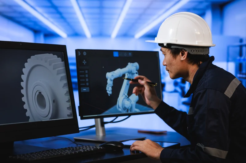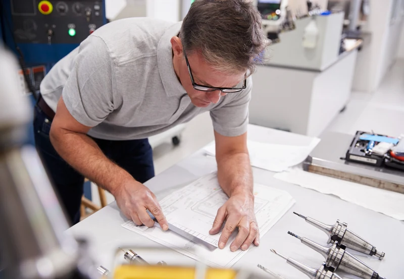

A finite element analysis can be mathematically correct and still answer the wrong engineering question. The model may show acceptable stress and deflection, but the real component is manufactured in a specific material condition, with altered or more complex geometry driving an unforseen load path, overly conservative connection methods, fixturing conditions, and process history. If those details are simplified too aggressively, the analysis can create confidence without accurately representing the hardware that will be built and used.
That is why useful FEA starts before the solver runs. The engineering team has to decide what the model is meant to represent, which assumptions matter, and how the results will be checked against physical reality.
Start With the Real Load Case, Not the CAD Model
A robust CAD model is a convenient starting point, but it is not the operating environment. Structural components, lifting equipment, fixtures, test equipment, and manufactured assemblies develop loads through interfacing supports, fasteners, contact surfaces, actuators, gravity, motion, and operator or process inputs.
The first question should be: what is the part or assembly actually expected to do?
- Where does the load enter the structure?
- How is the component supported or restrained?
- Are contacts fixed, sliding, bolted, pinned, welded, or allowed to separate?
- Which load combinations represent normal operation, upset conditions, handling, or testing?
- Does the model need to target stiffness and deflection as closely as the stress reaction?
Simple boundary conditions that make the model stable are not automatically boundary conditions that make it realistic. An unrealistically fixed support can shift load paths and suppress movement that would occur in the real assembly. Determining the proper constraints in a simulation model is the core challenge for the engineer; it is many times an iterative path to proper constraints as modes of deformation are progressively uncovered in the results. Early iterations typically present either too many or not enough degrees of freedom in a simulation model. Refining the constraints to get to the proper range and manner of movement in the device is fully dependent on the experience of the FEA engineer.
Material Data Has to Match the Decision
Material selection in an FEA model is more than choosing a familiar grade from a software library. The properties that matter depend on the analysis and the design question.
For a basic linear static study, elastic modulus and Poisson’s ratio may be enough to predict stiffness and elastic stress distribution. Other applications may require yield behavior, plasticity, temperature-dependent properties, fatigue data, orthotropic behavior, or properties tied to a specific manufacturing condition.
For manufactured components, the engineering team should also ask whether the real process can create direction-dependent behavior, residual stress, local property changes, or geometry that differs meaningfully from the nominal CAD model. If those factors could change the design decision, they belong in the validation plan even if they are not all represented directly in the first analysis.
Manufacturing Assumptions Can Change the Model
A welded assembly can behave differently from an idealized continuous solid. A machined part may include radii, pockets, surface conditions, or tolerances that influence a local result. A fixture may introduce preload or constraint. An additively manufactured component may have build orientation, raster direction, layer behavior, and process-dependent properties that are not captured by treating the printed part as a uniform material.
The practical question is not whether every manufacturing detail belongs in every finite element model. It is whether omitting a detail could change the engineering decision.
That distinction keeps the model useful. It avoids both extremes: a simplified model that hides important behavior and an unnecessarily complicated model that consumes time without improving the answer.
A Good FEA Deliverable Explains Its Assumptions
A stress plot by itself does not tell a reviewer enough to judge the analysis. The deliverable should make the engineering assumptions visible.
- Geometry included, removed, or simplified
- Material properties and their source or basis
- Loads, load combinations, and how they were applied
- Supports, contacts, joints, fasteners, or other boundary conditions
- Mesh strategy and areas that required refinement
- Criteria used to interpret stress, deflection, stability, or other results
- Known limitations and conditions that still require physical validation
This makes the analysis easier to review, reuse, and challenge. It also separates a calculated result from the engineering judgment used to create the model.
Use Physical Testing to Answer What the Model Cannot
FEA can narrow risk and focus the engineering effort, but it does not eliminate the need for physical validation in every application. The right test depends on the question the project still needs to answer.
For example, strain gauges can compare measured strain at selected locations with predicted behavior. Load testing can verify stiffness, deformation, or structural response under a controlled condition. Dimensional inspection can show whether a manufacturing process is producing geometry close enough to the model assumptions. Prototype testing can expose contact, assembly, wear, stability, or process behavior that is difficult to predict confidently in simulation.
The strongest validation plan uses analysis and testing for different jobs. Simulation helps explain and predict behavior across a design. Testing provides physical evidence at the points where uncertainty matters most.
Treat FEA as an Engineering Validation Process

The better question is not, “Can we run FEA on this?” It is, “What decision are we trying to make, and what combination of analysis, engineering judgment, manufacturing information, and testing will support that decision?”
That approach is especially useful when a project involves structural components, lifting devices, custom fixtures, test equipment, or manufactured assemblies. In each case, the result has to connect back to how the hardware will actually be built, constrained, loaded, inspected, and used.
ENSER supports FEA as part of that broader engineering process. The objective is not to produce a more impressive contour plot. It is to build an analysis that represents the problem closely enough to help the customer make a defensible design or validation decision.
Before You Trust the Result, Check the Assumptions
Before using an FEA result to approve a design, change a component, or define a test, review the assumptions behind it. Ask what is known, what was simplified, what could materially change the result, and what should be verified physically.
A useful analysis does more than calculate stress. It creates a traceable engineering argument between the model, the manufactured hardware, and the decision the team needs to make.
If you are deciding whether FEA makes sense for your design, ENSER can help review the problem and define the right level of analysis and validation.
Technical Review by Mike Wahner
Senior FEA & Simulation Engineer
30+ years of engineering experience at ENSER
Frequently Asked Questions
Why do manufacturing assumptions matter in FEA?
Manufacturing assumptions can affect geometry, material behavior, stiffness, load paths, contacts, and boundary conditions. If an assumption can change the engineering decision, it should be represented in the analysis or addressed through physical validation.
What should an FEA report include?
A useful FEA report should document the geometry and simplifications, material properties, loads, boundary conditions, contacts or joints, mesh strategy, evaluation criteria, results, limitations, and recommended validation steps.
Does FEA replace physical testing?
Not in every application. FEA can predict behavior and focus the testing effort, while physical testing can verify real hardware behavior and address uncertainty that is difficult to represent confidently in the model.
How can strain gauges be used with FEA?
Strain gauges can measure strain at selected locations during a controlled load test. Engineers can compare these measurements with predicted strain or structural behavior to evaluate whether the model represents the physical system closely enough for the intended decision.
When should manufacturing details be included in an FEA model?
Include manufacturing details when they can materially affect stiffness, stress, load transfer, deformation, failure mode, or the decision being made. Other details can often be handled as documented assumptions or through targeted physical testing.