Equipment with a heavy moving assembly creates a difficult balance. The mechanism must control the load as it moves downward without requiring excessive operator force to return it to position.
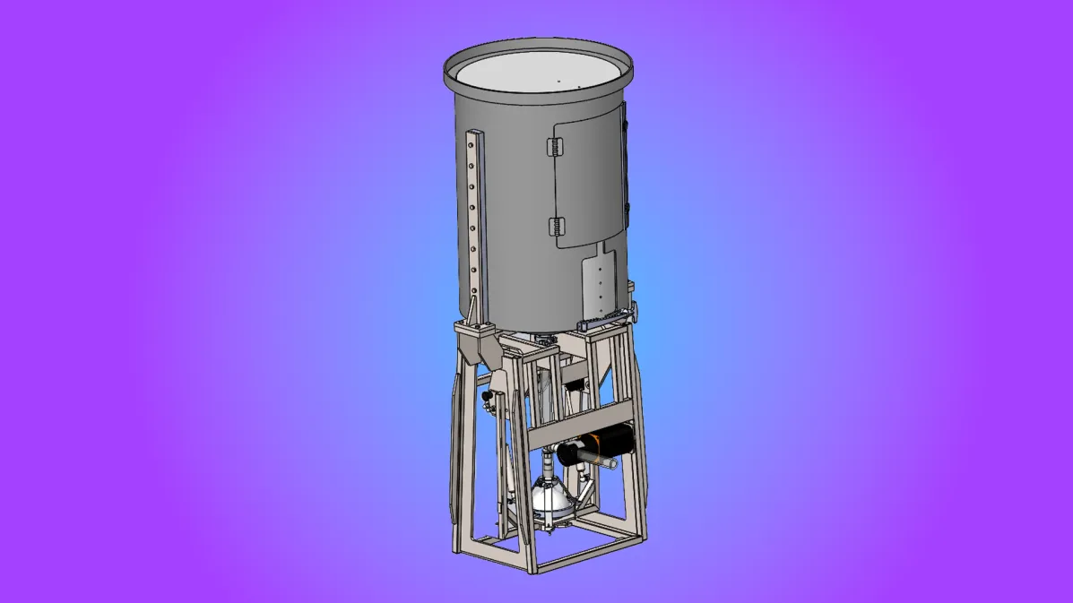
CPBiotools needed a custom apparatus that could support and reposition a diaphragm pump between a vertical operating position and an angled draining position. The same equipment also had to carry a 200-liter process-fluid tank with an approximate loaded weight of 500 pounds.
ENSER approached the equipment as one integrated mechanical system. Structural analysis, dynamic CAD modeling, force calculations, gas-spring sizing, damping, and manufacturing requirements all had to work together in a manufacturable stainless-steel design.
The Challenge: Support the Load Without Losing Control
The moving pump assembly could not be allowed to fall freely as it traveled toward the draining position. At the same time, adding too much resistance or gas-spring force would make the assembly unnecessarily difficult for an operator to raise.
The frame also had to support the overhead process load while meeting the customer’s functional and visual expectations for a fully welded stainless-steel system.
One Structure Had to Solve Several Interacting Requirements
How could one manufacturable stainless-steel structure support the overhead process load while controlling the pump assembly’s movement without creating excessive operator effort?
Solving one requirement without considering the others could create a new problem elsewhere. A heavier frame could affect geometry and movement. A different pivot location could change the center of gravity. A stronger gas spring could support more of the load but increase the effort needed to move the assembly in the opposite direction.
Engineering the Frame and Mechanism as One System
- Dynamic CAD modeling
- Force and load calculations
- Finite element analysis
- Structural frame design
- Gas-spring sizing
- Damping and motion control
- Manufacturing and fabrication considerations
This system-level approach was necessary because a change to one part of the design could affect several others. Frame stiffness influenced geometry. Geometry influenced the moving load and center of gravity. Gas-spring capacity and mounting locations affected both falling behavior and operator effort.
FEA Shows Where the Frame Needs More Stiffness
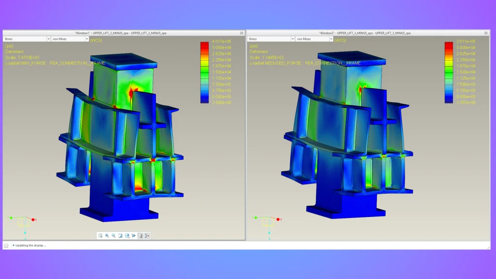
ENSER used finite element analysis to evaluate the frame under the overhead fluid load.
The analysis identified areas where the long, relatively thin legs required additional stiffness. Instead of making the entire frame heavier, the design could add material locally where the analysis showed reinforcement was needed.
Dynamic CAD Models Evaluate the Full Range of Motion
ENSER also developed versioned motion models representing the operating, draining, and intermediate positions of the moving assembly.
- How the load changed throughout the range of motion
- Gas-spring force requirements
- Potential gas-spring attachment locations
- Operator effort
- Falling-load behavior
A moving mass can produce substantially different forces as its position and center of gravity change. Evaluating only the starting and ending positions would not provide the same understanding of the mechanism’s behavior throughout its travel.
Balancing Gas-Spring Assistance and Operator Effort
Gas springs were incorporated to help manage the moving load, while a vane damper provided additional motion control.
The design needed to strike a workable balance. Too little assistance could allow the pump assembly to move downward too aggressively. Too much gas-spring force could make the equipment difficult for an operator to return to its operating position.
From the Engineering Model to Physical Equipment
A physical unit was built and demonstrated. According to the project recap, the frame supported the live-load design intent, while the simulation identified where additional stiffness was needed.
The demonstration added an essential source of information: real-world feedback. Further refinement of the falling-load behavior was expected after the demonstration, allowing observations from the physical equipment to guide the next design iteration.
Engineering Takeaway: Design Structure and Motion Together
Developmental equipment works best when structure, movement, operator effort, and fabrication are treated as parts of the same engineering problem.
In this project, combining FEA, dynamic modeling, force calculations, motion-control components, and manufacturing experience produced a working physical system and a clearer path for refinement.
Technical Review by Mike Wahner
Senior FEA & Simulation Engineer
30+ years of engineering experience at ENSER
Frequently Asked Questions
What was the custom positioning equipment designed to do?
The system was designed to support and position a diaphragm pump between a vertical operating position and an angled draining position. It also supported a 200-liter process-fluid tank with an approximate loaded weight of 500 pounds.
Why was finite element analysis used on the frame?
FEA was used to evaluate the stainless-steel frame under the overhead fluid load. The analysis identified areas where the long, relatively thin legs needed additional stiffness, allowing reinforcement to be added locally rather than making the entire frame heavier.
How did dynamic CAD modeling help design the mechanism?
Dynamic CAD models represented the operating, draining, and intermediate positions of the moving assembly. The models provided force information for evaluating load changes, gas-spring requirements, attachment locations, operator effort, and falling-load behavior throughout the mechanism's travel.
Why were both gas springs and a vane damper used?
The gas springs helped manage the moving load, while the vane damper provided additional control over the movement. The combination was evaluated to prevent the assembly from moving downward too quickly without making it unnecessarily difficult for an operator to raise.
Why should structure and motion be engineered together?
Structural stiffness, component geometry, pivot position, center of gravity, gas-spring force, and operator effort influence one another. Designing them together helps prevent a change intended to solve one requirement from creating a new problem elsewhere in the system.