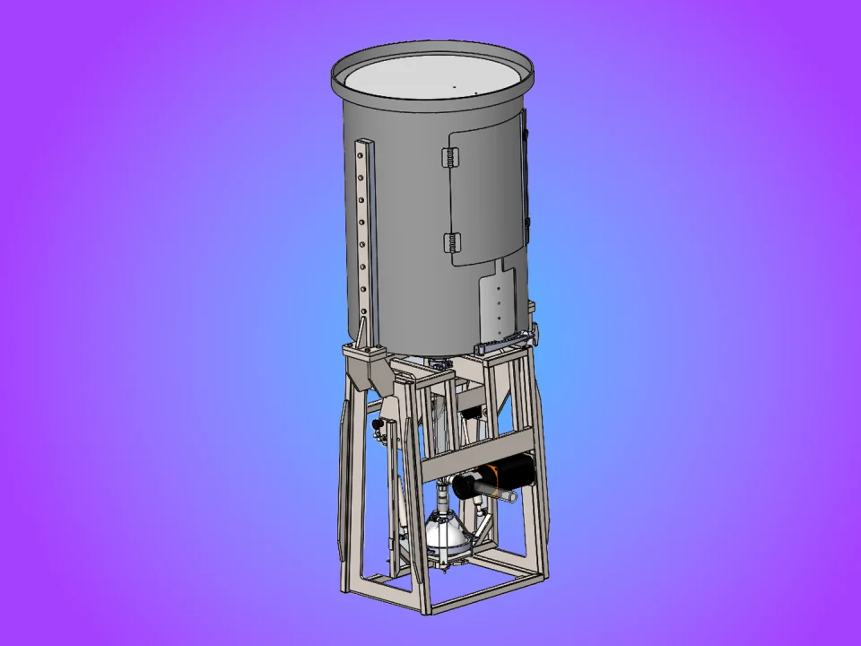



When a structural device will carry a substantial field load, verifying its overall strength is only part of the job. Engineers also need to understand how forces travel through the assembly and whether its connections help or interfere with that load path.
Following a column-buckling event in a New York City high-rise, engineers were developing a structural solution to raise a series of beams and girders back toward level. Plan B Engineering needed additional confidence in a paired, expanding steel jacking device before it was used in the field.
ENSER used finite element analysis (FEA) to evaluate the device under the anticipated lifting forces. The analysis uncovered localized stresses around two welded areas and led to a counterintuitive conclusion: removing selected welds could improve the way the primary structural members carried the load.
The Structural Challenge
The project team needed to determine whether the jacking device would behave as intended under substantial loading. Overall strength was important, but it was not the only concern.
The welded connections affected how forces moved between the structural members. The team needed to understand whether those connections distributed the load effectively or created localized stress concentrations that should be addressed before field use.
What the Analysis Needed to Answer
- Would the jacking device respond as intended under the anticipated lifting forces?
- Were the welded connections helping distribute the load, or were they creating localized areas of concern?
Answering these questions before field use gave the project team an opportunity to evaluate the design without relying only on drawings, conventional calculations, or engineering intuition.
Modeling the Structure and Its Welded Connections
Because the device was symmetrical, ENSER modeled 50 percent of the structure. This reduced the size of the simulation while preserving the structural behavior the analysis needed to capture.
The weld configuration required particular attention. Weld features were modeled explicitly so the simulation would not treat structural members as connected where no physical connection existed.
Loads and grounding constraints were applied using the known operating conditions. Reaction forces were also monitored as a check that the model was responding as intended.
ENSER performed multiple simulations while refining the model and evaluating both maximum loading and force levels more representative of the expected field conditions.
FEA Identifies Localized Weld Stresses
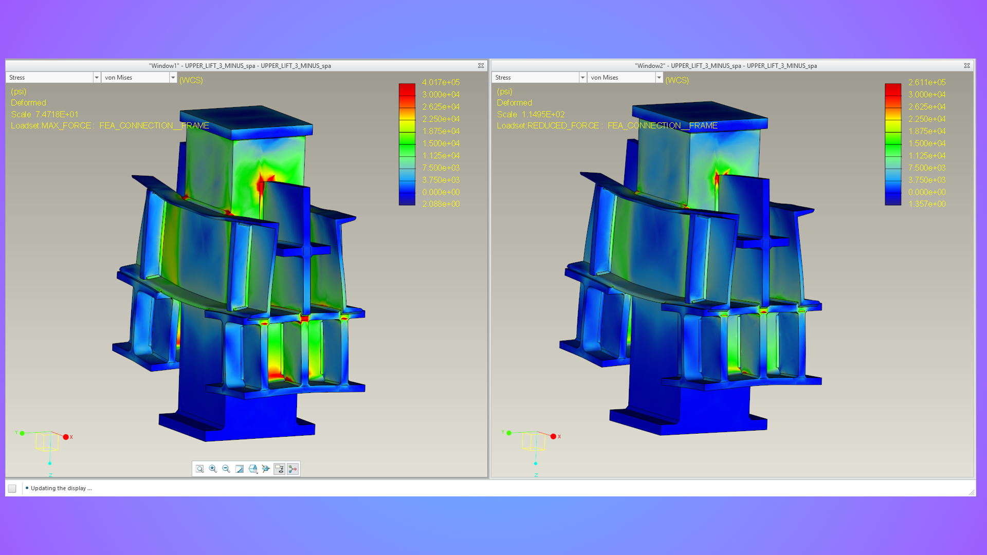
The initial analysis identified localized stress concentrations around two welded areas.
The finding led to a design change that might not have been obvious from the drawings alone. Instead of adding material or installing additional welds, the analysis indicated that strategically removing selected welds allowed the primary structural members to carry and redirect the load more effectively.
In this application, more connection was not necessarily better. The location and behavior of the connections mattered more than the total amount of welding.
Testing a Revised Load Path
ENSER updated the model to reflect the relieved weld configuration and performed additional simulations. The revised structure was evaluated at force levels closer to the expected field condition.
These secondary and tertiary analyses allowed the project team to compare the revised configuration with the original design before the equipment was placed into service.
Simulation Supports the Design Decision
The revised jacking device performed satisfactorily in the simulations, and the calculated stress levels met the project’s safe-loading criteria.
Initial and enhanced analysis results were developed within 3 to 4 days. This gave the project team useful design information without introducing a lengthy analysis cycle.
The analysis findings and revised design conclusion were then provided to the site for review and group acceptance.
Engineering Takeaway: The Load Path Decides
More connection is not always better. The load path decides.
Welds can strengthen an assembly, but they also influence how forces move between structural members. In this case, FEA showed that selected welds were contributing to localized stress rather than helping the primary members distribute the load.
For structural equipment with unusual geometry, loading, or connections, finite element analysis can expose load-path behavior that may not be apparent from drawings or conventional calculations alone.
Technical Review by Mike Wahner
Senior FEA & Simulation Engineer
30+ years of engineering experience at ENSER
Frequently Asked Questions
How was finite element analysis used on the jacking device?
Finite element analysis was used to evaluate how the jacking device responded to the anticipated lifting forces. The model helped engineers examine overall structural behavior, reaction forces, welded connections, and localized stress concentrations before the device was used in the field.
Why were the welds included in the FEA model?
The welds affected how loads transferred between the structural members. Modeling them explicitly prevented the simulation from assuming that members were connected in areas where no physical weld existed and provided a more useful representation of the actual load path.
Why would removing welds improve a structural design?
A weld changes the stiffness and force transfer between connected members. In this application, selected welds contributed to localized stress concentrations. Removing those welds allowed the primary structural members to carry and redirect the load more effectively.
Did the revised jacking-device design meet the project criteria?
According to the project recap, the revised configuration performed satisfactorily in the simulations, and calculated stress levels met the project's safe-loading criteria. The findings were provided to the site for review and group acceptance.
When should FEA be considered for a welded structure?
FEA can be useful when a welded structure has unusual geometry, substantial loading, complex connections, or an uncertain load path. It can help engineers identify stress concentrations and compare design changes before hardware is committed to service.