


The Brayton cycle is a thermodynamic process that occurs in jet engines and all other gas turbine engines too. It describes how the engine is able to produce work through heat and energy. In the case of the jet engine, the work generated in a propulsive thrust
When analyzing the thermodynamic processes inside an engine, engineers usually divide the engine based off the major thermodynamic processes like compression, combustion and expansion. Below is a simplified schematic of an engine, with each divided segment labeled with a station number.
As the air enters the inlet and moves from station 0 to 1, the air is compressed. The compression process should preferably be adiabatic, meaning heat neither enters nor leaves during the process and isentropic, meaning entropy remains the same throughout the process. While in the compressor, the temperature and pressure of the air raises.
While keeping the pressure constant, as the air moves through the combustor from station 1 to 2, fuel is added to the flow. The newly introduced fuel is then combusted, increasing the temperature further.
The gas then begins to expand as it enters the turbine and moves from station 2 to 3. During this expansion, work is done on the turbine. This work is then transferred through a shaft to both the compressor and the nozzle, producing thrust and accelerating the engine forward.
The diagram above depicts an ideal Brayton cycle. In reality, the processes characterize as isentropic or adiabatic are not perfectly fixed in heat or entropy. Instead of vertical or horizontal lines in the ideal Brayton cycle, jet engines usually result in slanted lines. Although they’re not completely the same, the Brayton cycle is still valuable for evaluating a jet engine as they are still very similar.
Engine efficiency
A critical part of designing a jet engine is assessing and gauging how efficient it is. The more efficient an engine is, the less fuel it needs to consume to create thrust.
Jet engine efficiency is usually defined as the ration between propulsive power and fuel power.
In the above equation for overall efficiency, T is thrust, U0 is the flight velocity, mf is the flow rate of the fuel mass and hf is the specific fuel energy per unit mass. Overall efficiency can also be calculated by taking the product of two different specific efficiencies, thermal and propulsive efficiency.
Thermal efficiency
The thermal or internal efficiency of an engine is the efficiency at which it can convert fuel into kinetic energy. It’s often written as the ration between fuel power and the rate at which kinetic energy is produced.
In the above equation, me is the flow rate of the exhaust mass and Ue is the exhaust velocity.
Jet engines with higher temperatures and pressure ratios have a higher thermal efficiency. The thermal efficiency is often limited by the materials used in the jet engine. The higher the temperature, the more stress the materials have to withstand without melting or mechanically failing.
The temperature in most combustors can reach up to 2,300° C. For comparison, the surface of the sun is around 5,600° C. In order to handle this temperature without melting, the jet engines made by Rolls-Royce use a special nickel alloy coated with a thin layer of ceramic, but even with this special high-temperature-resistant plating the combustion chamber would still melt. To avoid this, a series of laser-driller holes helps funnel cooler air from the compressor to cool the combustion chamber.
Propulsive efficiency
The propulsive, or external efficiency of an engine is the efficiency at which an engine can convert kinetic energy to propulsive thrust. To have a high propulsive efficiency, engines must have a propelling mechanism that depletes very little energy during the conversion process. It’s often described as the ratio between the production rate of propulsive kinetic energy and the propulsive power.
In order to maximize propulsive efficiency, the engine needs a configuration that produces a large thrust, while still maintaining the smallest change in velocity across the engine. To accomplish this, the engine must be able to move a large volume of air. An engine with a lower flight velocity than its exhaust velocity will waste energy, producing a low propulsive efficiency.
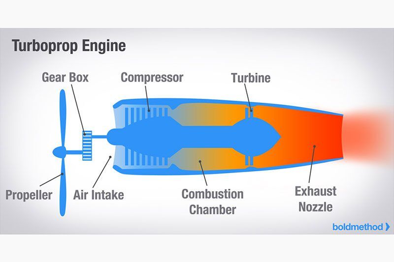
The speed of the jet also has an effect on the propulsive efficiency. When a high velocity jet exhaust enters a low velocity airstream, a lot of energy is lost. At low speeds, a turbojet is not very efficient. Using a configuration called a turboprop to drive a propeller is much more efficient use of the work produced by a jetengine. This advantage begins to diminish at around 400 mph as the blades reach supersonic speeds. At these
speeds, the blades begin to create shock waves, reducing the efficiency.
A turbofan engine has the advantages of both a turbojet and a turboprop, providing better propulsive efficiency at both low and high airspeeds. Using more machinery and only slightly more fuel, the turbofan is able to move a much larger volume of air and generate more thrust compared to the turbojet
Engineering Services
Whether you need engineering services for the world’s largest power rollers or something smaller, ENSER Corp, has the engineering skills and know-how to complete your project.
